In the case of steel castings full annealing is
the only way for completely effacing the coarse grains and Widmanstätten structure,
with its associated brittleness.
The following properties of a 0,3 % carbon steel illustrate the
improvement obtained by annealing:
Table 1
| |
BH |
YP
MPa |
TS
MPa |
El
% |
Cold
Bend |
Izod
J |
| Cast |
160 |
309 |
448 |
6 |
45° |
12 |
| Annealed 880°C, 6hr, furnace cooled |
153 |
247 |
479 |
24 |
165° |
32 |
The Widmanstätten structure can be modified into a "feathery"
arrangement of the ferrite by the influence of silicon. This is shown in
Fig. 1 which consists of a portion of the boundary-ferrite, Widmanstätten
and feathery structures. Fig. 2 shows the macroform of the primary
crystals, revealed by the segregation of the impurities. The effects of
this segregation have to be effaced as much as possible by annealing and
this necessitates temperatures higher than those used for worked
steels.
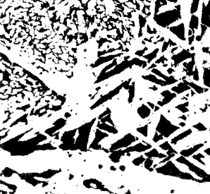
Figure 1. Micro-structure of same steel sho-wing part of ferrite
network, Widmanstätten and feathery structure. Ferrite-white.
Pearlite-dark ( x 80) |
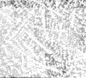
Figure 2. Macro-structure of cast steel revea-ling large prirmary
austenite crystals due to presence of impurities (x4) |
An imperfect anneal is illustrated by Fig. 3, in which the original
cast structure is still outlined by the deposition of the ferrite in the
old positions, especially around the inclusions. They can be prevented by
double annealing.
Double annealing consists of heating the steel to a temperature
considerably over the A3 point, cooling rapidly to a temperature below the
lower critical range and then immediately reheating to a point just over
the upper critical point (Ac3), followed by slow cooling.
This method is particularly useful for castings. The high temperature
treatment effaces the strains, coalesces the sulphide films in the ferrite
which embrittle the steel and produces homogenity by rapid diffusion. The
quick cooling prevents the coarse deposition of the ferrite in the large
grains, but tends to harden the metal. The second heating refines the
coarse grains and leaves the steel in a softened condition. A typical
structure, which is shown in Fig. 4, should be compared with Fig. 3.
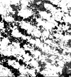
Figure 3. Same steel imperfectly annealed ferrite formed in
masses outlining original cast structure (x80) |
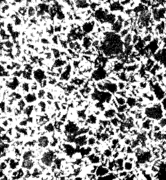
Figure 4. Same steel properly annealed: ferrite and perlite uniform and fine (x80) |
Softening Tool and Air-hardening Steels
To soften high carbon and air-hardening steels, in order to allow
machining operation to be carried out, they are heated just below the
lower change point (650-700°C), causing. the cementite to balls-up into
rounded masses (i.e. spheroidising anneal). When the cementite is in this
condition high carbon steels can be cold drawn; but too high a temperature
causes pearlite to be reformed, with consequent high resistance to
deformation.
It should be remembered, however, that coarse laminated cementite
spheroidises extremely slowly, and the above treatment is therefore
carried out on a "hardened" material, obtained by suitable cooling from
above A3 or after cold working. A short cycle anneal consists of heating
just above Ac1, cooling below Ar1 and then raising temperature just below
Ac1 for 8 hours. Although the softest condition is obtained when the large
globules of cementite are embedded in the ferrite, a smooth machined
surface is difficult to obtain due to tearing. Groups of large globules
cause failure of sharp-edged cutting tools.
During the subsequent hardening operations, the time required to
dissolve fine spheroidised cementite is less than for the lamellar type.
This property is being used in hardening thin sections, such as safety
razor blades and needles, in order to reduce decarburisation.
Annealing and Hardening Temperatures for Tool Steels
The annealing or hardening temperatures of steels containing more than
0,9% carbon is just above the lower critical point (730-790°C) instead of
above the upper range.
Fig. 5 shows the appearance of a 1,3% carbon steel cast, in which the
cementite exists as brittle networks and plates. This type of structure
must be replaced by rounded particles of cementite in a fine pearlite
before hardening, otherwise cracks will propagate through the continuous
masses of brittle cementite.
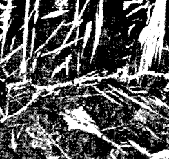
Figure 5. As cast: cementite network and plates in pearlite (x
100)
|
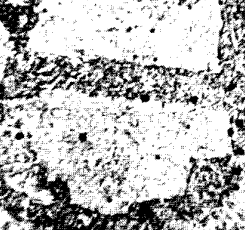
Figure 6. Heated to 1050°C and quenched in water. Large grains
(x 100)
|
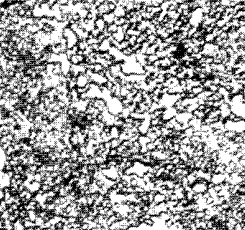
Figure 7. Cementite globules in properly hot-worked steel (x 200)
|
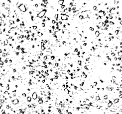
Figure 8. Cementite globules in martensite, in hardened steel (x 200)
|
The upper critical line rises steeply with increasing carbon content
above 0,87% and an excessively high temperature is required to dissolve
all the free cementite. This tends to develop coarse austenite crystals
which cause the steel to become brittle and cracks to form on quenching.
This grain growth is shown on Fig. 6, which is the structure of steel
quenched from 1050°C. On the other hand, particles of cementite restrain
grain growth.
Forging is, therefore, carried out through the critical range in order
to disperse the free cementite. This is followed by annealing at about
760°C (just above Ac1), to ball-up the free cementite and to remove
strains. Fig. 7 shows the structure formed. Even a fine cementite network
structure would cause trouble when drastic quenching is used, such as for
files. Fig. 8 shows the structure of a steel hardened from 760°C,
consisting of particles of cementite dispersed in a matrix of
martensite.
Products of Quenching: Cnstituents of Hardened Steel
The equilibrium diagram indicate the changes which occur under the slow
cooling conditions of annealing. The rapid rates of cooling necessary to
harden a steel cause the austenite to persist to a lower temperature and
to transform into a variety of micro-constituents discussed below.
Austenite is sometimes present with martensite, in drastically quenched
steels (Fig. 9). It cannot be completely retained in carbon steels by even
drastic quenching, but suitable additions of alloying elements allow the
retention of this constituent, for example 18/8 austenitic stainless
steel. This austenite consists of polyhedral grains, showing twins (Figs.
9 and 10). It is non-magnetic and soft.
Martensite is the hardest constituent obtained in a given steel, but
the hardness increases with the carbon content of the steel up to 0,7%.
The micro-structure exhibits a fine needle-like structure, which becomes
more pronounced when the steel is quenched from high temperatures. See
Figs. 9 and 11.

Figure 9. Forms of carbide in micro-constituents in
steel
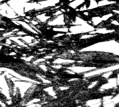
Figure 10. Martensite needles (dark) in austenite (x1200)
|
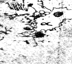
Figure 11. Steel (C, 0,4) quenched from between A1 and A3. Undissolved ferrite arou-nd inclusion in martensite (x 100)
|
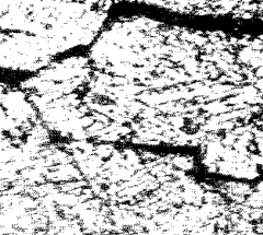
Figure 12. Martensite and quench crack. Steel (C, 0,5) quenched in water from 900°C(x400)
|
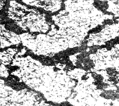
Figure 13. Nodular troostite in martensite (x400)
|

Figure 14. Sorbite in quenched and tempered (600°C) steel (C, 0,5) (x500)
|
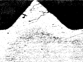
Figure 15. Case-hardened screw. Cracked martensitic case (white), martensite and fer-rite core (x30) |
The nature of martensite has not been definitely agreed upon, but for
the present purpose it might be considered to be highly stressed a-iron
which is supersaturated with carbon. The fc.c. lattice of g-iron is
equivalent to a body centred tetragonal lattice with ratio 1,414. The
tetragonal lattice of martensite is formed from this by compressing its
height and increasing its cross-section. A slight further compression to
give a ratio of 1 gives rise to a-iron.
Bainite, which occurs in alloy steels, has a rapidly etched needle-like
structure, somewhat resembling tempered martensite. As the temperature of
its formation becomes higher the acicular nature becomes less accentuated,
the needles increasing in size
Troostite (nodular) rapidly etches black and is practically
unresolvable under the ordinary microscope. Special microscopic technique
has shown that nodular troostite is a mixture of radial lamellae of
ferrite and cementite. Therefore it differs from pearlite only in degree
of fineness and carbon content which is the same as that in the austenite
from which it is formed. Figs. 9 and 13 show a typical
martensite-troostite structure; nodules outline the boundaries of the
original austenite grains. Troostite is softer than martensite and small
amounts in the steel lessen the risks of cracking and distortion.
Some confusion arises as to the nomenclature of micro-constituents
found in hardened and tempered steels. The terms troostite and sorbite are
frequently used to indicate constituents formed during quenching and also
during tempering. In the former case (quenching) the cementite always
occurs in a laminated form, while in the latter (tempering) it has a
granular form. Hence, the term troostite has been adopted in this book for
constituents possessing a laminated structure. Sorbite is used to denote
the granular structures.
List of Articles - Knowledge Base